
Today we’ll talk about filters and warmth. Most people have heard about the ubiquitous LP and HP, also known as the low pass and high pass filters. The low pass filter concept essentially shaped (all puns intended) the landscape, or soundscape, of synthesizer-driven music from the onset. Robert Moog applied for a patent on his filter design in 1966 and began a legacy of synthesizer and filter architecture that stretches to today and undoubtedly into the future.
Synthesis is not the only use of filters, however; the concept of filters, better known as equalization, was conceived in the early days of telephone technology.
In fact, we owe much thanks to Bell Laboratories, and others, for paving the way in audio signal research. A great deal of signal loss otherwise known as attenuation was discovered in long cable runs.
This attenuation was frequency dependent: meaning it was not a uniform loss in amplitude. Had it been a uniform attenuation it could have been corrected with a uniform amplitude boost. Instead, special circuits were designed to even-out or equalize the attenuation. A circuit that acts upon a certain range, or band, of frequencies is known as a filter (Davis 244).
Filter Basics
Cutoff – The cutoff is described as the frequency where the signal has dropped 3 dB relative to the unaffected region. This generally applies to Low Pass and High Pass types while Band Pass and Band Stop (Notch) have a center frequency dictating where the filter is acting.
Slope – Beyond the cutoff, the filter will exhibit increasing attenuation until the prescribed amount is reached. The rate at which the attenuation occurs is defined in dB per octave. Generally, one circuit element, or pole, attenuates 6 dB per octave. Thus a 2-pole filter will exhibit 12 dB attenuation per octave, or slope, and a 4-pole filter has a 24 dB slope (Davis 256).
Resonance/Emphasis – In many ways cutoff and resonance have become intrinsic in the world of synthesis and sound design. The idea is simple – feeding some of the output back into the filter which effectively boosts the amplitude of the cutoff region. The effect it has on the sound can range from subtle boosting, or emphasizing, to dramatic spectral altering. In some filter designs increasing the resonance to its maximum value will cause the filter to “self-oscillate.” Then, it produces a sine wave at its cutoff frequency. This sine wave is often more pure than an oscillator can produce. By modulating the cutoff of a self-oscillating filter a certain sound can be achieved. This technique has been widely used throughout synthesis music. Although some may consider it cliché, it is truly classic (ode to Kraftwerk).
Analog, Non-linearity and the quest for Warmth
Before the DAW revolution people did not obsess over warmth. Warmth was being introduced inside every circuit. It was in nearly every step from microphone to amps, to compressors, on through to tape, and finally cut into vinyl. No doubt engineers still concerned themselves with the overall amount of warmth, or saturation, or even noise being introduced in every step of recording. It was scarce for an engineer to describe his equipment with terms like “sterile” or “cold.” Those of us making music strictly ITB, in the box, are not strangers to the idea of cold, harsh, and lifeless sound emanating from our speakers. You can’t even throw a digital rock without hitting a post on a forum prescribing ways to introduce warmth into your otherwise dull digital sounds.
What exactly is this elusive magic known as warmth and where does it come from?
Let us define “magic” as a lack of knowledge leading to a perceived phenomenon. Then it is easy to understand how the “magic” of engineering can elude us. Warmth is a subjective term. It finds its way into our vocabulary so often and it does little to reveal an understanding. It obscures us from the truth.
Non-linearity is defined as “possessing a characteristic shape that is not a straight line… an analog device in which plot of output against input is not a straight line” (Collins 282). To simplify: a signal passing through a linear system will pass unaltered and a non-linear system will alter the signal. Sometimes this type of alteration is the addition of harmonics not present in the original signal. In audio equipment this is measured as Total Harmonic Distortion, THD, and it is present in all analog circuitry high fidelity audio equipment is designed to exhibit the lowest possible THD.
Harmonics are frequencies present in a signal that are integer multiples of the fundamental. The fundamental frequency is the lowest frequency present in a signal which our brains perceive as the defined pitch. If a bass sound has its fundamental at 60hz we perceive it to be roughly a B1: a true B1 is 61.74hz. The harmonics are derived from this fundamental as integer multiples (i.e. 60×2 60×3 60×4 etc. etc.) and would be 120, 180, 240, 300 ad infinitum. A cursory web search will yield useful harmonic calculators (search that phrase).
Harmonic calculators can be used in a plethora of ways and are especially useful for harmonic equalization: a topic for another day. It is important to note, especially dealing with harmonic distortion, harmonics are generally grouped by even, or odd, or both.
Even harmonics are octaves of the fundamental and thus, musically important. Odd harmonics are not necessarily un-musical. They help provide character to the sound. Truly, we could talk at great lengths about harmonics, their importance, and their relationships with sound. However, this survey should be enough to help you understand the effects of distortion.
Distortion acts in different ways. Typical “saturation” distortion is known as soft-clipping. It compresses both peaks, positive and negative, of the wave form in an equal amount, this is known as symmetrical distortion and produces odd order harmonics. The compression is not the same as a compressor but rather it squeezes down the wave form peaks immediately while rounding the edges.
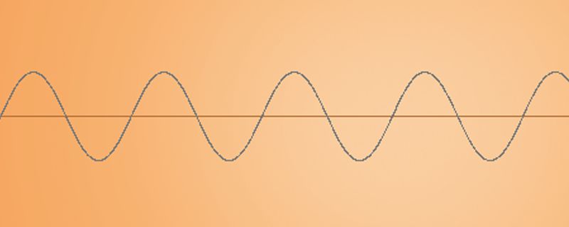
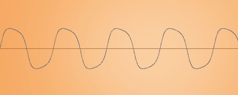
Compare the two images. Notice how the peaks are uniformly compressed or flattened with soft edges on the image below. After applying some distortion, the sine wave looks somewhat similar to a square wave.
So how does this help to illuminate our discussion of warmth?
Analog equipment is rife with nonlinearities, no matter how small or unperceivable. As they begin to stack up, and with careful control over them, the addition of harmonics can increase the complexity and fullness of a sound.
I must stress this next point emphatically. There are many different ways in which various analog equipment imparts distortion. Do not think that merely passing through imperfect, theoretically speaking, circuits is all it takes to make records sound magical. There are many different forms of distortion in this vein: tape saturation, tubes, aka valves and transformers all add to the idiosyncrasies of sought after vintage gear. For an in-depth look at analog warmth please refer to the Sound On Sound February 2010 article entitled Analogue Warmth.
Digital Tundra
Now we understand how analog equipment imparts character. Furthermore, we can look at what is missing from digital systems. Analog equipment is subject to a number of unpredictable influences: voltage fluctuations, heat present in the equipment, and any number of subtle differences that may occur. These imperfections breathe life into our works and over the years we have all become accustomed to hearing them in music.
I wonder if in a parallel universe digital had preceded analog (somehow) would we be writing of ways to reduce warmth in our gear? If over decades of listening to clean digital recordings would we shudder at the sound of THD? Would we be able to perceive it even at the smallest amounts? We cannot really know these answers, but an in depth study of psychoacoustics (don’t tempt me I’ll do it!) might reveal our brains are wired to enjoy perceivably complex sounds. I digress.
The problem (if you can call it that) is digital systems are too perfect. Without flaws and subtle imperfections digital systems impart nothing to the signal. Computer code (the backbone of digital) repeats identically time after time and is not subject to the same subtle of analog equipment. Today many companies are pioneering new innovative ways of overcoming this sterility. By careful examination of analog gear companies are able to emulate the characteristics that are appealing or musical and incorporate it in ways that are controllable.
This can be done in a general way such as emulating the nonlinearities of an analog circuit or it can be done in painstaking ways by analyzing vintage gear down to every single circuit in order to bring life to a digital emulation. Roland has pioneered new methods (for better or worse) coined Analog Circuit Behavior which attempts to better model the idiosyncrasies of an analog system into a digital system (in truth they may have just changed the title of an otherwise widely used method known as Analog Circuit Emulation ACE). Again this is a survey of an otherwise complex topic and I encourage you to dig deeper if this is something that interests you.
A tutorial by Travis Basso
2 Comments
Great article! Usually I hate reading about music production (instead of hearing and watching it), but this is thought-provoking.
Consider this a temptation to write about those thoughts on psychoacoustics.
Loved this tutorial! Thanks for explaining signal basics and analog warmth. I have been using things like filter and resonance on my synths but never understood why it is they do what they do.